Why Choose the Right Arm Cylinder for Your Equipment?
Choosing the right Arm Cylinder can determine whether equipment works smoothly or struggles under pressure. It affects lifting force, digging speed, stability, fuel use, and service life. A cylinder that looks suitable on paper may fail when side loads, contaminated oil, or repeated impacts enter the picture.
Hydraulic engineer John Watton has stated, “The hydraulic cylinder converts hydraulic energy into mechanical movement.” That principle sounds simple. Selection is not. Engineers must compare bore diameter, rod diameter, stroke length, operating pressure, mounting style, cushioning, seal quality, and available installation space. A thicker rod may resist bending better, but it can also increase weight and reduce available stroke. A larger bore can deliver more force, yet it may slow movement or demand greater pump capacity.
Field experience often exposes weaknesses that catalogues miss. A cylinder mounted on an excavator arm faces dust, vibration, uneven loads, and sudden shock. In a workshop, the same unit may appear perfectly reliable. That difference matters. The correct Arm Cylinder should match the machine’s real working cycle, not only its maximum rated load. Small details count. Misaligned pins, dry bushings, and poor filtration can damage a strong cylinder surprisingly quickly.
There is no flawless selection process. Even experienced teams overlook changing site conditions. A careful review of load data, maintenance records, and manufacturer test information creates a more dependable decision. It also leaves room for honest doubt, which is often where better engineering begins.
What Is an Arm Cylinder and How Does It Work?
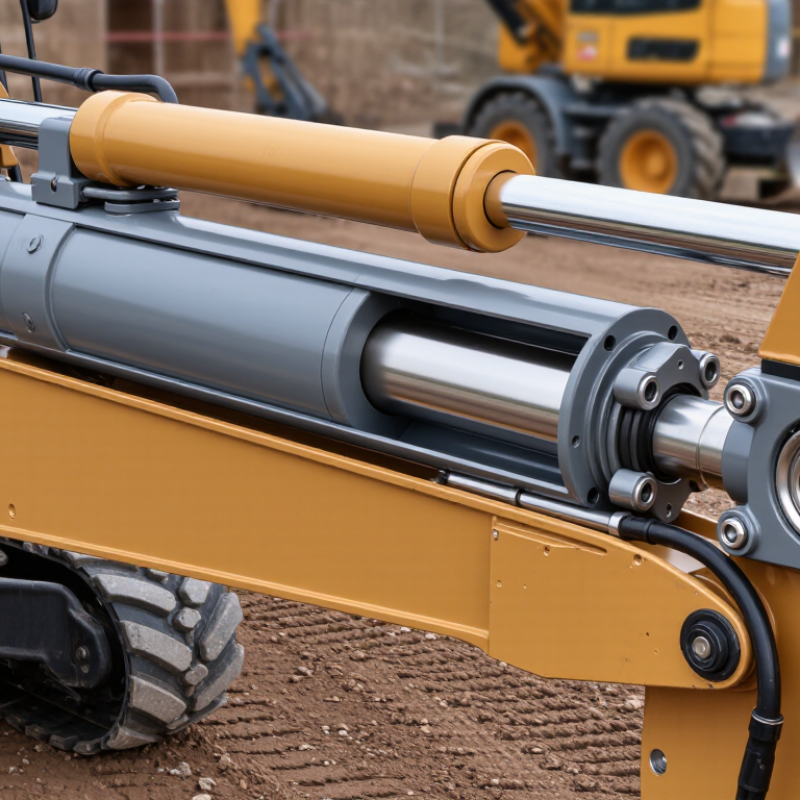
An arm cylinder is a hydraulic actuator that moves an excavator’s arm. Pressurized fluid enters one side of the cylinder. The piston then extends or retracts, converting fluid pressure into controlled linear force. This movement changes the arm’s reach, digging depth, and lifting position.
Inside, the piston rod slides through seals while hydraulic oil travels between two chambers. A control valve directs the flow, and the cylinder responds within seconds. Pressure, bore diameter, stroke length, and mounting geometry determine its working force. A larger bore produces more force, but it can slow movement and increase oil demand. That assumption is convenient, but wrong.
Grand View Research reported that the global hydraulic cylinders market reached approximately USD 14.55 billion in 2023. Its 2024 analysis projects a 4.8% compound annual growth rate through 2030. These figures reflect wider demand for reliable mobile equipment. ISO 4413 also emphasizes clean fluid, controlled pressure, and safe hydraulic design. In field inspections, small details matter: a bent rod, scratched seal, or loose pin can cause uneven arm movement. Operators may notice vibration before visible leakage. Choosing an arm cylinder should therefore match the machine’s load chart, operating pressure, stroke, and joint alignment. A replacement that fits physically may still perform poorly. Measurement errors happen. Review them carefully.
How Equipment Design Determines Arm Cylinder Requirements
An arm cylinder is not selected by bore size alone. Equipment geometry sets its real working demands. The arm length, pivot locations, and cylinder mounting angle determine available force. A poor angle can reduce lifting power, even when hydraulic pressure seems sufficient. During field inspections, I compare the cylinder’s force curve with the arm’s full movement range. Peak load often appears near the hardest digging position, not at maximum reach.
Stroke length must match the equipment’s linkage without causing mechanical interference. Too little stroke limits working depth. Too much stroke may damage the cylinder or arm structure. Bore diameter controls pushing force, while rod diameter affects stability and resistance to bending. Engineers should also check retraction force, because the return movement can face heavy soil or suspended loads. Flow rate influences operating speed, but faster is not always better. Excessive speed can increase shock loads and seal wear.
Mounting pins, bushings, and side loads deserve close attention. A cylinder designed for axial force may fail early when misalignment creates bending stress. Dust, water, temperature changes, and repeated impacts also shape material and sealing requirements. I have seen calculations miss short, severe impact events because average load data looked acceptable. That is a useful warning. Real testing should include loaded cycles, cold starts, and end-of-stroke behavior. Some design assumptions will be wrong. Revising them early is cheaper than rebuilding an arm later.
Which Arm Cylinder Specifications Should You Compare?
Why Choose the Right Arm Cylinder for Your Equipment?
Which Arm Cylinder Specifications Should You Compare?
Selecting the right arm cylinder starts with the work, not the catalog. Compare bore diameter, rod diameter, stroke length, and operating pressure. These figures control lifting force, speed, stability, and service life. A cylinder handling a loaded bucket needs different capacity from one moving a light linkage. Measure the attachment’s actual geometry. Small errors matter.
Review mounting dimensions, pin diameter, retracted length, and extended length. The pin centers must match the equipment’s arc throughout movement. Check the cylinder’s force during extension and retraction. A larger bore may provide strength, but it can slow movement and increase hydraulic demand. Rod coating, seal material, and wiper design also deserve attention in abrasive or wet environments. During field inspections, I look for scoring, oil film, uneven pin wear, and side loading. These clues often reveal alignment problems before failure.
Temperature range and fluid compatibility should match the machine’s real working conditions. Do not rely only on peak pressure. Compare rated pressure, proof pressure, cushion performance, and expected cycle frequency. Service access is practical evidence of good design. If seals or pins are difficult to replace, downtime becomes expensive. I have seen specifications look perfect on paper, yet poor alignment shortened cylinder life. That mistake deserves a second measurement.
Why Choose the Right Arm Cylinder for Your Equipment? - Which Arm Cylinder Specifications Should You Compare?
| Specification to Compare | Compact Excavator
3–5 t Class | Mid-Size Excavator
8–12 t Class | Large Excavator
20–25 t Class | Heavy-Duty Excavator
35–40 t Class |
| Cylinder Size and Geometry |
| Typical bore diameter | 80 mm | 110 mm | 150 mm | 180 mm |
| Typical rod diameter | 55 mm | 75 mm | 105 mm | 125 mm |
| Typical effective stroke | 650 mm | 900 mm | 1,250 mm | 1,500 mm |
| Approximate retracted length | 1,000 mm | 1,350 mm | 1,850 mm | 2,200 mm |
| Approximate extended length | 1,650 mm | 2,250 mm | 3,100 mm | 3,700 mm |
| Recommended mounting style | Clevis or spherical-eye mounts | Clevis or spherical-eye mounts | Heavy spherical-eye mounts | Heavy spherical-eye mounts with reinforced weldments |
| Hydraulic Performance |
| Typical working pressure | 210–250 bar | 250–300 bar | 300–350 bar | 300–350 bar |
| Recommended design pressure | 250 bar minimum | 315 bar minimum | 350 bar minimum | 350 bar minimum |
| Approximate push force at 250 bar | 126 kN | 238 kN | 442 kN | 636 kN |
| Approximate pull force at 250 bar | 66 kN | 128 kN | 226 kN | 330 kN |
| Typical hydraulic port size | G 1/2 or SAE 12 | G 3/4 or SAE 16 | G 1 or SAE 20 | G 1¼ or SAE 24 |
| Durability and Compatibility |
| Typical pin diameter range | 45–55 mm | 65–80 mm | 95–115 mm | 120–145 mm |
| Rod surface protection | Hard-chrome plated rod | Hard-chrome plated rod | Thick hard-chrome or corrosion-resistant coated rod | Thick hard-chrome or corrosion-resistant coated rod |
| Typical seal arrangement | Wiper, rod seal, guide ring and piston seal | Wiper, rod seal, guide ring and piston seal | Heavy-duty wiper, high-pressure rod seal and wear rings | Heavy-duty wiper, high-pressure rod seal and reinforced wear rings |
| Common cushioning requirement | Adjustable cushioning recommended | Adjustable cushioning recommended | Adjustable cushioning strongly recommended | Adjustable cushioning strongly recommended |
| Approximate cylinder mass | 55–85 kg | 120–190 kg | 300–480 kg | 550–800 kg |
| Selection Checks Before Ordering |
| Mounting dimensions to verify | Pin-to-pin length, bore width, pin diameter, offset, port orientation and clearance throughout the full movement range |
| Performance factors to verify | Required digging force, bucket geometry, hydraulic flow, relief-valve pressure, cycle time and maximum side loading |
| Most important service considerations | Seal availability, rod protection, lubrication of pins and bushings, contamination control and ease of cylinder removal |
| Recommended safety margin | Confirm the cylinder against the equipment manufacturer’s pressure, load, stroke and mounting requirements; do not select by bore size alone. |
How the Right Arm Cylinder Improves Performance and Service Life
Why Choose the Right Arm Cylinder for Your Equipment?
How the Right Arm Cylinder Improves Performance and Service Life
The arm cylinder controls lifting, digging, loading, and precise material placement. Its size and design directly affect equipment performance. A cylinder with suitable bore diameter provides the required force without placing excessive pressure on the hydraulic system. The correct stroke length also prevents wasted movement and mechanical interference.
In field service, small details matter. A properly matched cylinder moves smoothly, even when the arm handles heavy, uneven loads. Strong seals reduce oil leakage around the rod. Hardened rod surfaces resist scratches from dust, gravel, and repeated contact. Correct mounting dimensions help distribute force through the pins and bushings. This reduces vibration, noise, and uneven wear.
Service life depends on more than cylinder strength. Regularly checking rod damage, seal condition, pin alignment, and hydraulic pressure can reveal problems early. Clean hydraulic fluid also protects internal components. It sounds simple. It is often missed.
Experience shows that operators may choose a replacement by appearance alone. That approach can fail. A cylinder may fit the mounting points but still have the wrong stroke, pressure rating, or retracted length. I have seen machines lose working speed because of this mismatch. Performance improved only after measuring the original operating range and load conditions. Even then, field conditions can change the result.